 Phone: (971) 568337007

Blog
API 682 Seal Plans Explained: How to Choose the Right Flushing Plan for Mechanical Seals

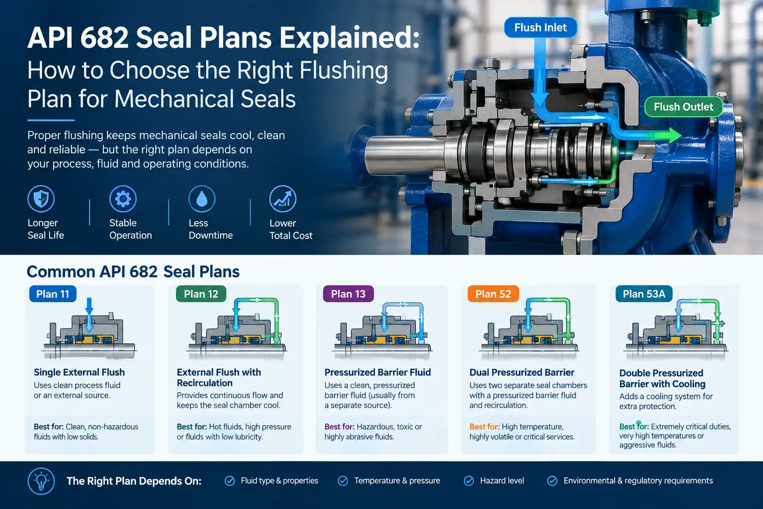
In many industrial plants, the real issue is not the carbon face, the silicon carbide ring, the spring, or even the elastomer. The real issue is what happens around the seal every single day. Is the seal chamber too hot? Is the fluid vaporizing at the seal faces? Are solid particles accumulating where they should never be? Is the barrier fluid pressure stable? Is the flush line blocked? Is the pump running dry during startup?
This is where API 682 seal plans become critical.
A mechanical seal may be perfectly designed, correctly specified, and installed by an experienced technician. But without the right flushing, cooling, sealing, buffering, or barrier arrangement, it can still fail prematurely. In high-risk oil, gas, petrochemical, chemical, wastewater, LNG, and hydrogen applications, the seal plan is not a minor accessory. It is part of the reliability strategy.
This guide explains API 682 seal plans in practical language. You will learn what seal plans do, how they affect seal life, which plans are used for different operating conditions, and how to choose the right flushing plan for pumps, agitators, and rotating equipment. We will also connect the topic to related engineering decisions such as mechanical seal failure troubleshooting, double vs single mechanical seals, seal material selection, and AI predictive maintenance for pumps and seals.
What Is an API 682 Seal Plan?
An API 682 seal plan is a standardized arrangement used to control the environment around a mechanical seal. It defines how fluid is moved, cooled, filtered, pressurized, buffered, or separated from the seal faces.
The term comes from API 682, the American Petroleum Institute standard for shaft sealing systems for centrifugal and rotary pumps. API 682 is widely used in oil, gas, refining, petrochemical, and chemical processing industries because it provides a common language for seal designers, plant engineers, maintenance teams, and equipment suppliers.
If you want a broader introduction to the standard itself, our earlier article, Mechanical Seals for Petrochemical Plants: API 682 Guide to Prevent Failure, explains why API 682 matters in demanding process environments.
A seal plan can include several functions:
- Flushing: Moving fluid across the seal faces to remove heat and contamination.
- Cooling: Reducing seal chamber temperature using external or internal cooling.
- Sealing: Providing a clean fluid barrier between the process fluid and atmosphere.
- Buffering: Using an unpressurized or low-pressure fluid to support a dual seal.
- Barrier pressurization: Maintaining a higher-pressure clean fluid between two seal faces in a dual seal arrangement.
- Filtration or separation: Removing solids before they damage the seal faces.
- Vapor suppression: Preventing the process fluid from flashing or boiling at the seal interface.
In simple terms, a seal plan is the life-support system for a mechanical seal.
A pump can move fluid. A seal can stop leakage. But the seal plan decides whether the seal operates in a clean, cool, stable, and lubricated environment or in a destructive one.
Why Seal Plans Matter More Than Many Engineers Expect
Many maintenance teams focus on the seal cartridge, the face materials, or the brand. Those are important. But field experience repeatedly shows that seal failures are often caused by process conditions, not by the seal alone.
Consider a hot hydrocarbon pump. The seal faces may be made of high-quality silicon carbide. The elastomers may be correctly selected. The installation may be perfect. But if the seal chamber temperature rises above the fluid’s vapor pressure, a vapor film can form between the faces. The seal loses lubrication. Heat increases. The faces crack. The plant experiences another unplanned shutdown.
Or consider a wastewater pump handling gritty slurry. A standard single seal may look adequate on paper. But if solids accumulate in the seal chamber, they can embed into the softer face and scratch the harder mating ring. Within weeks, the seal leaks. The problem was not only the seal design. The problem was the absence of proper flushing or separation.
This is why seal plans are so important. They help control the five major enemies of mechanical seals:
- Heat
- Dry running
- Contamination
- Pressure instability
- Chemical or phase-change effects
For a deeper diagnostic perspective, see our Pump Seal Troubleshooting Guide 2026, which explains how failure timing can reveal whether the root cause is installation, process conditions, material incompatibility, or inadequate seal support.
The Operating Conditions That Decide Your Seal Plan
There is no universal “best” API 682 seal plan. The correct plan depends on the actual service conditions.
Before selecting a flushing or barrier arrangement, engineers should evaluate the following variables.
Operating Condition Why It Matters Seal Plan Implication Fluid cleanliness Solids can score seal faces or block flush lines Plans with filtration, external flush, or cyclone separation may be needed Temperature High heat can vaporize fluid and degrade elastomers Cooling plans such as Plan 21, 23, or barrier systems may be required Pressure High pressure can open seal faces or overload secondary seals Balanced seals, dual seals, and pressurized barrier plans may be preferred Vapor pressure Volatile fluids can flash at the seal face Pressurized barrier systems such as Plan 53 or 54 may be necessary Toxicity or flammability Leaks create safety and environmental risk Dual seals with barrier fluid and monitoring are often specified Lubricity Poorly lubricating fluids cannot maintain a fluid film Clean barrier or buffer fluid can protect the faces Pump type Centrifugal pumps, agitators, and compressors have different seal chamber behavior Plan selection must match equipment geometry and operating profile Startup and shutdown Dry running or thermal shock may occur during transients Protection, interlocks, and stable barrier pressure become more important Emissions requirements Fugitive emissions regulations may restrict leakage Dual seal systems with controlled barrier fluid are often preferred Maintenance access Complex plans require monitoring and trained operators Simplicity and reliability must be balanced with process risk
Material compatibility is also part of the equation. A seal plan can fail if the barrier fluid, elastomers, metals, or secondary seals are not compatible with the process. For that reason, seal plan selection should always be reviewed together with How to Select the Right Seal Material for Oil, Gas & Chemical Industries.
Common Seal Problems That a Proper Flush Plan Can Prevent
A good seal plan does not magically make a wrong seal correct. But it can prevent many of the most common failure mechanisms.
1. Overheating at the Seal Faces
Mechanical seals generate heat due to friction. A thin fluid film between the faces provides lubrication and cooling. If the seal chamber becomes too hot, that film can break down.
Cooling-oriented plans help remove heat before it damages the faces. This is especially important in hot oil, condensate, refinery, and chemical services.
2. Dry Running
Dry running is one of the fastest ways to destroy a mechanical seal. Without fluid, friction can raise face temperature dramatically in seconds. The result may be cracked carbon, glazed faces, melted elastomers, or warped components.
Some plans provide external clean fluid to maintain lubrication. Others rely on barrier systems to keep the seal environment stable. In critical services, dry-run protection and monitoring should be part of the overall strategy, as discussed in our AI Predictive Maintenance for Pumps & Seals article.
3. Solid Particle Accumulation
In slurries, wastewater, catalyst-bearing fluids, or dirty process streams, particles can collect in the seal chamber. These particles can embed into softer seal faces and act like abrasive paste.
Plans that inject clean fluid, filter the flush stream, or separate solids before they reach the seal can significantly extend service life. For wastewater and slurry applications, our article Wastewater Pumps: Common Sealing Challenges and Their Proven Solutions explains why external flush and dual seal arrangements are often necessary.
4. Vaporization and Flashing
Volatile fluids can vaporize at the seal face even if the bulk process temperature appears acceptable. Once vapor forms, lubrication is lost. The seal may run dry locally, overheat, and fail.
Pressurized barrier systems help keep the seal interface stable by maintaining a clean fluid at a pressure higher than the process pressure. This is common in hazardous, flammable, or environmentally sensitive services.
5. Barrier Fluid Contamination
In dual seal systems, the barrier fluid must remain clean. If process fluid leaks into the barrier system, the barrier fluid can become contaminated, lose lubricity, or damage the outer seal.
Monitoring pressure, temperature, level, and leakage trends is essential. This is another area where predictive maintenance can add value by detecting abnormal behavior before a failure becomes visible.
6. High-Pressure Face Instability
In high-pressure pumps, hydraulic forces can push seal faces apart. If the closing force is insufficient, leakage increases and the seal becomes unstable.
Dual seals with properly controlled barrier pressure can balance these forces. For a detailed comparison, read Double vs Single Mechanical Seals: High-Pressure Guide.
API 682 Seal Plans Explained One by One
The following sections explain the most commonly referenced API 682 seal plans. Not every plan is suitable for every plant, and local codes, company standards, and equipment manufacturer recommendations may affect final selection.
API Plan 11: Recirculation from Pump Discharge
What it does:
Plan 11 recirculates fluid from the pump discharge back to the seal chamber. The flow is usually controlled by an orifice.
Typical use:
Clean, cool to moderately hot fluids where the discharge fluid is suitable for seal lubrication and cooling.
Advantages:
- Simple and economical
- Widely understood
- Useful for many clean centrifugal pump services
- Requires no external fluid source
Limitations:
- Not suitable for dirty fluids unless filtration is added
- May not provide enough cooling for very hot services
- Can fail if the orifice or line becomes blocked
- Not ideal for volatile fluids without additional control
Plan 11 is often one of the first plans engineers consider because it is straightforward. However, simplicity should not be mistaken for suitability. If the pumped fluid contains solids, crystallizes, polymerizes, or has poor lubricity, Plan 11 may accelerate failure instead of preventing it.
API Plan 12: Discharge Recirculation with Strainer
What it does:
Plan 12 is similar to Plan 11 but includes a strainer to protect the seal chamber from particulates.
Typical use:
Cleaner services where small amounts of solids may be present and need to be filtered before reaching the seal.
Advantages:
- Adds basic solids protection
- Still relatively simple
- Useful when discharge fluid is otherwise acceptable for sealing
Limitations:
- Strainer requires monitoring and cleaning
- A plugged strainer can starve the seal of flush flow
- Not sufficient for heavy slurry or highly abrasive services
Plan 12 can be a good middle ground, but only if the plant maintains the strainer. A blocked strainer can turn an apparently protective plan into a dry-running risk.
API Plan 13: Recirculation from Seal Chamber to Pump Suction
What it does:
Plan 13 moves fluid from the seal chamber back to the pump suction.
Typical use:
Services where the seal chamber needs to be kept cooler or where suction conditions allow stable recirculation.
Advantages:
- Can help manage seal chamber temperature
- Uses process fluid, so no external source is required
- Useful in certain clean, low-to-moderate temperature applications
Limitations:
- Depends heavily on pump suction conditions
- May not be suitable for volatile fluids
- Can introduce air or vapor issues if not properly designed
- Requires careful hydraulic evaluation
Plan 13 is not as universally simple as it may appear. The pump suction pressure, NPSH margin, fluid vapor pressure, and system stability all matter. If the recirculation line disturbs suction conditions, the plan can create new problems.
API Plan 14: Seal Chamber to Suction with Strainer
What it does:
Plan 14 is similar to Plan 13 but includes a strainer.
Typical use:
Cleaner services where some particulate control is needed while recirculating from the seal chamber to suction.
Advantages:
- Adds filtration to a suction-return arrangement
- Can help keep the seal chamber cleaner
Limitations:
- Strainer maintenance is essential
- Not suitable for heavy solids
- Sensitive to suction-side hydraulic conditions
Like Plan 12, Plan 14 depends on discipline. If the strainer is ignored, the system may quietly lose flush flow.
API Plan 21: External Flush with Cooling
What it does:
Plan 21 introduces a clean external fluid into the seal chamber and usually includes cooling. The exact routing depends on the installation and system design.
Typical use:
Hot or moderately contaminated services where the process fluid alone is not ideal for seal cooling.
Advantages:
- Improves temperature control
- Can dilute or remove heat from the seal chamber
- Useful when process fluid has poor sealing characteristics
Limitations:
- Requires a reliable external fluid source
- Increases system complexity
- Must manage compatibility between flush fluid and process fluid
- May not be suitable where dilution is unacceptable
Plan 21 is often considered when heat is the main enemy. However, the external fluid must be clean, compatible, and available under stable pressure. A flush system that fails intermittently can be worse than no flush system at all.
API Plan 22: External Flush with Controlled Drain
What it does:
Plan 22 uses an external clean fluid and manages the discharge in a controlled way, often when returning fluid to the process is not acceptable.
Typical use:
Applications where clean flush fluid is needed but process contamination or dilution must be avoided.
Advantages:
- Provides clean fluid to the seal chamber
- Can isolate the seal from dirty process conditions
- Useful when the flushed fluid cannot be returned to the process
Limitations:
- Consumes external fluid
- Requires drainage handling
- May not be economical for continuous large-flow services
- Needs environmental and safety review
Plan 22 can be effective, but operators must understand the fluid balance. If the drain becomes restricted, pressure behavior in the seal chamber may change unexpectedly.
API Plan 23: Recirculation with Pumping Ring and Cooler
What it does:
Plan 23 uses a pumping ring to circulate fluid from the seal chamber through a cooler and back into the system.
Typical use:
Hot clean services where active cooling is needed and process fluid loss must be minimized.
Advantages:
- Strong cooling capability
- Closed-loop arrangement reduces product loss
- Useful for high-temperature clean fluids
- Can maintain more stable seal chamber conditions
Limitations:
- More complex than Plan 11
- Requires cooler maintenance
- Pumping ring adds mechanical complexity
- Not ideal for dirty or crystallizing fluids
Plan 23 is often a serious option for hot oil, refinery, and high-temperature process pumps. It can be highly effective when the fluid is clean enough to circulate repeatedly without plugging the cooler.
API Plan 31: Recirculation with Cyclone Separator
What it does:
Plan 31 uses a cyclone separator to remove solids from the fluid circulating through the seal chamber.
Typical use:
Services containing moderate solids where separation can protect the seal faces.
Advantages:
- Helps reduce solids at the seal interface
- Can extend seal life in dirty services
- Uses process fluid rather than a large external flush
Limitations:
- Cyclone performance depends on flow and particle size
- Not suitable for very high solids loads
- Requires proper installation orientation and maintenance
- May need supplemental flushing in severe service
Plan 31 is a practical solution when solids are present but not overwhelming. It is not a cure-all for heavy slurry. In severe wastewater or mining applications, external flush or dual seal systems may be more appropriate.
API Plan 32: External Injection of Clean Fluid
What it does:
Plan 32 injects clean external fluid into the seal chamber to dilute, cool, or flush contaminants.
Typical use:
Abrasive slurries, crystallizing fluids, dirty process streams, wastewater, and applications where seal chamber cleanliness is critical.
Advantages:
- Actively keeps the seal chamber cleaner
- Can reduce temperature and solids concentration
- Useful for harsh slurry services
- Often more reliable than relying on process fluid alone
Limitations:
- Requires a clean, compatible external fluid source
- Consumes flush fluid
- Must control pressure to avoid process contamination or seal chamber issues
- Needs monitoring to confirm flow is present
Plan 32 is one of the most important plans for dirty services. If you are dealing with wastewater, sludge, grit, fibers, or abrasive particles, this plan often becomes part of the baseline strategy. Our Wastewater Pumps: Common Sealing Challenges and Their Proven Solutions article explains why external flush and robust seal materials are frequently combined in these environments.
API Plan 41: Simple External Flush Arrangement
What it does:
Plan 41 is generally used for simple external flush arrangements where clean fluid is supplied to the seal chamber and managed according to system requirements.
Typical use:
Applications where a basic clean fluid supply is sufficient and process dilution or drainage is acceptable.
Advantages:
- Can be straightforward
- Provides clean fluid to the seal area
- Useful in selected low-risk services
Limitations:
- Not suitable for highly hazardous or volatile fluids
- Requires reliable external fluid supply
- Must be evaluated for environmental and process compatibility
Plan 41 should not be selected simply because it sounds easy. The key question is whether the external fluid is truly clean, compatible, and available under all operating conditions.
API Plan 51: Buffer Fluid System for Dual Seals
What it does:
Plan 51 provides an unpressurized or low-pressure buffer fluid arrangement for dual seal systems.
Typical use:
Dual seal applications where a clean buffer fluid is needed but high-pressure barrier control is not required.
Advantages:
- Simpler than fully pressurized barrier systems
- Provides clean fluid support to the seal faces
- Can reduce process fluid exposure to the atmosphere
Limitations:
- Less effective for volatile or high-risk fluids
- Buffer pressure control is limited
- Requires monitoring of fluid level and condition
Plan 51 can be useful, but it is not the strongest option for highly hazardous services. When process fluid is volatile, toxic, flammable, or expensive, engineers often move toward pressurized barrier arrangements.
API Plan 52: Unpressurized Reservoir for Dual Seals
What it does:
Plan 52 uses an unpressurized reservoir to supply buffer fluid to a dual seal system.
Typical use:
Less severe dual seal applications where a clean buffer fluid is needed without full pressurization.
Advantages:
- Lower complexity than Plan 53
- Provides a reservoir for buffer fluid
- Can be cost-effective for selected services
Limitations:
- Not ideal for volatile fluids
- Limited pressure control
- Reservoir condition must be monitored
- May not meet strict emissions or safety requirements
Plan 52 is often viewed as a practical intermediate solution. However, if the process fluid can vaporize or leak easily, an unpressurized system may not provide enough stability.
API Plan 53: Pressurized Barrier Fluid System
What it does:
Plan 53 maintains a pressurized clean barrier fluid between the faces of a dual seal. Common variations include bladder accumulator and piston accumulator designs.
Typical use:
Hazardous, toxic, flammable, volatile, abrasive, or environmentally sensitive services.
 Read More :
Oil Seal vs O-Ring: Key Differences and Applications
Advantages:
- Keeps barrier pressure above process pressure
- Prevents process fluid from escaping to atmosphere
- Provides clean lubrication to seal faces
- Supports stricter emissions and safety requirements
- Can handle difficult fluids better than single seal arrangements
Limitations:
- Higher initial cost
- Requires accumulator, piping, instrumentation, and maintenance
- Barrier fluid must be compatible and monitored
- System complexity increases training requirements
Plan 53 is one of the most important seal plans in modern petrochemical and oil and gas practice. When reliability, safety, and emissions control matter, a pressurized barrier system is often the engineering answer.
For a broader comparison of seal arrangements, read Double vs Single Mechanical Seals: High-Pressure Guide. That article explains why double seals are not merely “two seals,” but a risk-management strategy supported by barrier fluid control.
API Plan 54: Pressurized Barrier with Circulation
What it does:
Plan 54 is a pressurized barrier system that often includes active circulation and cooling for the barrier fluid.
Typical use:
Demanding dual seal services where barrier temperature control and stable pressure are both important.
Advantages:
- Strong barrier fluid management
- Can maintain cleaner and cooler barrier conditions
- Suitable for severe service where heat buildup is a concern
- Supports high-reliability dual seal operation
Limitations:
- More complex and expensive
- Requires pumps, coolers, controls, and monitoring
- Maintenance team must understand the system
- Not always necessary for simple services
Plan 54 is typically considered when Plan 53 alone may not provide enough thermal control or when the barrier fluid needs active circulation to remain stable.
Summary Table: Common API 682 Seal Plans
| Seal Plan | Basic Function | Best Suited For | Main Caution |
|---|---|---|---|
| Plan 11 | Discharge recirculation to seal chamber | Clean, moderate-temperature pumps | Not for dirty or volatile fluids |
| Plan 12 | Discharge recirculation with strainer | Cleaner fluids with minor solids | Strainer plugging risk |
| Plan 13 | Seal chamber to suction recirculation | Selected clean services | Sensitive to suction conditions |
| Plan 14 | Seal chamber to suction with strainer | Light solids with suction return | Requires strainer maintenance |
| Plan 21 | External flush with cooling | Hot or moderately difficult fluids | Needs reliable external fluid |
| Plan 22 | External flush with controlled drain | Services where return is not acceptable | Fluid consumption and drainage |
| Plan 23 | Recirculation with pumping ring and cooler | Hot clean services | Complexity and cooler maintenance |
| Plan 31 | Recirculation with cyclone separator | Moderate solids | Not for heavy slurry |
| Plan 32 | External clean fluid injection | Slurries, wastewater, dirty fluids | Requires clean flush source |
| Plan 41 | Simple external flush arrangement | Selected low-risk services | Process compatibility |
| Plan 51 | Buffer fluid for dual seals | Less severe dual seal services | Limited pressure control |
| Plan 52 | Unpressurized reservoir for dual seals | Basic dual seal support | Not for highly volatile fluids |
| Plan 53 | Pressurized barrier system | Hazardous, volatile, high-risk fluids | Higher cost and complexity |
| Plan 54 | Pressurized barrier with circulation | Severe dual seal services | Requires active monitoring |
Single Seal Plans vs Dual Seal Plans
One of the most important decisions is not only which plan number to use, but whether the application requires a single seal arrangement or a dual seal arrangement.
A single mechanical seal has one primary sealing interface. If that interface fails, process fluid can leak to atmosphere. Single seals can be excellent choices for clean, low-risk, non-hazardous services. They are simpler, often less expensive, and easier to maintain.
A dual mechanical seal has two sealing interfaces with a barrier or buffer fluid between them. This arrangement provides an extra layer of protection. If the inner seal begins to fail, the barrier system can help prevent process fluid from escaping immediately.
The choice becomes especially important in high-pressure, high-temperature, volatile, toxic, flammable, or abrasive services. In those cases, the seal plan is not just improving performance. It is reducing consequence.
Our article Double vs Single Mechanical Seals: High-Pressure Guide explains the financial and operational logic behind this decision. A double seal may cost more upfront, but when downtime, emissions, safety incidents, and emergency labor are included, the total cost of ownership can favor the more robust arrangement.
In practical terms:
- Use simple flush plans for clean, low-risk services.
- Use external flush or separation plans when solids are present.
- Use cooling plans when heat is the dominant failure mechanism.
- Use dual seal barrier plans when leakage consequences are severe.
- Use pressurized barrier systems when volatile or hazardous fluids are involved.
How to Choose the Right Seal Plan: A Practical Decision Path
Selecting an API 682 seal plan should not be done by copying an old datasheet. Process conditions change. Fluid composition changes. Pump duty changes. A plan that worked five years ago may not be correct today.
Use the following decision path.
Step 1: Define the Fluid Honestly
Do not describe the fluid only by name. A fluid called “process water” may contain oil, chemicals, solids, dissolved gases, or temperature variations. Ask:
- Is the fluid clean or contaminated?
- Does it contain solids, fibers, crystals, or polymers?
- Is it flammable, toxic, corrosive, or environmentally sensitive?
- Does it have good lubricity?
- Does it vaporize easily?
- Can it be diluted safely?
For chemical and hydrocarbon services, material compatibility is critical. Review How to Select the Right Seal Material for Oil, Gas & Chemical Industries before finalizing the plan.
Step 2: Evaluate Temperature and Pressure
Identify normal, minimum, maximum, and upset conditions. Many seal plans fail because engineers design only for steady-state operation.
Ask:
- What is the maximum continuous temperature?
- What happens during startup, shutdown, or loss of flow?
- Is there pressure cycling?
- Are there water hammer or surge events?
- What is the vapor pressure at seal chamber temperature?
High-temperature clean services may require Plan 21, 23, or a dual seal barrier arrangement. High-pressure hazardous services may require Plan 53 or 54.
Step 3: Decide Whether the Process Fluid Can Be Used at the Seal
Some plans recirculate process fluid. Others introduce clean external fluid. Others isolate the seal completely with barrier fluid.
If the process fluid is dirty, crystallizing, polymerizing, abrasive, or chemically aggressive, relying on it alone may be risky. In those cases, Plan 32, Plan 53, or another isolation strategy may be more appropriate.
Step 4: Consider the Consequence of Failure
This is the question that separates technical selection from risk management.
If the seal leaks:
- Will it create a safety hazard?
- Will it cause environmental noncompliance?
- Will it shut down a critical production line?
- Will it damage bearings, couplings, or the shaft?
- Will it expose operators to toxic or flammable fluid?
If the answer is yes, the seal plan should be more robust. In many petrochemical plants, the cost of a barrier system is small compared to the cost of an incident.
Step 5: Check Maintenance Capability
A sophisticated plan can fail if the plant cannot maintain it.
Ask:
- Can operators monitor barrier pressure?
- Is there a procedure for checking flush flow?
- Are strainers and coolers accessible?
- Is there spare parts availability?
- Are technicians trained on the seal support system?
- Can alarms be integrated into the control system?
A plan that requires constant attention but receives none is a reliability risk.
Step 6: Link the Plan to the Seal Type
The seal plan must match the seal arrangement.
For example:
- A single seal may work with Plan 11 in clean service.
- A dirty slurry pump may need Plan 32.
- A hot clean pump may benefit from Plan 23.
- A hazardous volatile fluid may require a dual seal with Plan 53.
- An agitator in a corrosive tank may require a specially configured seal and support arrangement.
For agitator applications, Qalalam offers mechanical seal products such as Mechanical seals Agitator AUL44V, Mechanical seals Agitator AUH33, and Mechanical seals Agitator AUH11B, which can be considered depending on shaft size, tank conditions, speed, and fluid characteristics.
Industry-Specific Seal Plan Guidance
Different industries face different sealing challenges. The same plan number may be appropriate in one plant and dangerous in another.
Oil and Gas Processing
In oil and gas facilities, pumps may handle crude oil, condensate, produced water, amine solutions, sour gas liquids, and hydrocarbon streams. The sealing challenge is often a combination of pressure, temperature, abrasives, and safety risk.
Common considerations:
- Clean hydrocarbon services may use Plan 11 or Plan 13 if conditions allow.
- Hot services may require Plan 21, 23, or barrier cooling.
- Sour service requires material review under relevant standards.
- Hazardous fluids may require dual seals with Plan 53 or 54.
For broader technology context, see Advanced Mechanical Seals Boosting Efficiency in Oil & Gas.
Petrochemical Plants
Petrochemical plants often deal with aggressive chemicals, elevated temperatures, and strict reliability targets. Seal failure can trigger unplanned shutdowns, environmental issues, and safety incidents.
Important plan selection factors:
- Chemical compatibility of elastomers and metals
- Vapor pressure of the process fluid
- Solids or polymer formation
- Emissions requirements
- Availability of clean barrier fluid
In these environments, API 682 compliance is not just a procurement checkbox. It is a framework for reducing risk. Our article Mechanical Seals for Petrochemical Plants: API 682 Guide to Prevent Failure provides more detail on how the standard supports petrochemical reliability.
Wastewater and Slurry Pumps
Wastewater is one of the hardest environments for mechanical seals. It can contain grit, fibers, chemicals, oils, solids, and unpredictable variations.
Plans often considered:
- Plan 32 for external clean flush
- Plan 31 for moderate solids with cyclone separation
- Plan 52 or 53 for dual seal protection in severe service
Face materials also matter. Silicon carbide against silicon carbide is often preferred for abrasive service, while elastomer selection must match the chemical environment. For a full discussion, read Wastewater Pumps: Common Sealing Challenges and Their Proven Solutions.
Cartridge seals can also simplify maintenance in harsh wastewater environments. Models such as Mechanical seals Cartridge K22RSD and Mechanical seals Cartridge K23RRD may be relevant where pre-engineered installation and robust construction are priorities.
LNG and Cryogenic Services
LNG operates at extremely low temperatures, around -162°C. At these conditions, materials contract, elastomers behave differently, and conventional sealing assumptions may no longer hold.
Cryogenic sealing challenges include:
- Thermal contraction
- Material embrittlement
- Ice formation
- Loss of secondary seal flexibility
- Stable barrier fluid behavior at low temperature
Seal plan selection in LNG-related services must consider not only the plan number but also materials, insulation, trace heating, and monitoring. Our article How Global LNG Expansion Is Increasing Demand for Cryogenic Pump Sealing Systems explains why cryogenic reliability is becoming a strategic issue as LNG infrastructure grows.
Hydrogen Systems
Hydrogen presents a unique sealing challenge because the molecule is extremely small and can permeate many materials. Hydrogen embrittlement, leakage risk, and safety requirements make sealing design especially important.
In hydrogen pumps and related equipment, engineers often focus on:
- Low-leakage seal designs
- Compatible materials
- Stable pressure control
- Monitoring and detection
- Dual seal or non-contact approaches where appropriate
For a detailed overview, see Hydrogen Pumps and the Future of Seal Technology: Powering the Clean Energy Revolution.
Agitators and Mixers
Agitators are not always treated with the same engineering attention as pumps, but they can be just as demanding. The seal may be exposed to tank vapors, solids, viscosity changes, shaft deflection, and intermittent operation.
Agitator seal selection should consider:
- Shaft speed
- Tank pressure or vacuum
- Fluid abrasiveness
- Temperature
- Cleaning-in-place requirements
- Accessibility for maintenance
Qalalam’s agitator mechanical seal range includes options such as:
The correct model depends on application conditions, but the same principle applies: the seal and its support environment must be engineered together.
Secondary Seals: Why O-Rings Still Matter in Seal Plans
A seal plan may control the main sealing interface, but secondary seals can still make or break the system. O-rings, gaskets, and elastomeric secondary seals are used in glands, reservoirs, piping connections, accumulator systems, and seal housings.
If an O-ring is chemically incompatible, over-compressed, extruded, or damaged during installation, the entire seal support system can leak.
This is especially relevant in barrier fluid systems. A small leak in a Plan 53 reservoir or connection may seem minor, but it can lead to pressure loss, low barrier level, alarm fatigue, or eventual seal failure.
For practical guidance, review:
- Oil Seal vs O-Ring: Key Differences in Petrochemical Applications
- Why Do O-Rings Fail? Troubleshooting & Prevention Guide
- The Ultimate O-Ring Selection Guide 2025: Materials & Sizing
A reliable seal plan is not only about main faces. It is also about every secondary sealing point in the support system.
Maintenance and Monitoring: How to Keep a Seal Plan Working
Installing the correct API 682 seal plan is only the beginning. The plan must be operated and monitored.
A flush line can partially block. A cooler can lose effectiveness. An accumulator can lose pressure. A barrier reservoir can become contaminated. A strainer can plug. A pump can run at off-design conditions that change seal chamber behavior.
Useful monitoring points include:
- Barrier fluid pressure
- Barrier fluid temperature
- Barrier fluid level
- Flush flow rate where measurable
- Seal chamber temperature
- Vibration trends
- Leakage rate
- Alarm history
- Maintenance records
This is where digital maintenance becomes valuable. Our article AI Predictive Maintenance for Pumps & Seals explains how continuous monitoring and machine learning can detect abnormal patterns before they become visible failures.
For example, a slow rise in seal temperature may not trigger an immediate alarm, but it can indicate declining flush performance. A gradual change in barrier pressure may point to accumulator issues or leakage. Vibration patterns may reveal misalignment before the seal faces are damaged.
The best seal plan in the world cannot compensate for a plant that ignores warning signs.
Common Mistakes in Seal Plan Selection
1. Copying the Previous Design Without Reviewing Current Conditions
Plants change. Fluid composition changes. Temperature profiles change. A plan that was acceptable during commissioning may no longer be suitable after a process revamp.
2. Choosing the Cheapest Plan Without Considering Failure Cost
A simple Plan 11 may look attractive on a purchase order. But if it fails repeatedly, the cost of downtime, labor, environmental cleanup, and lost production can far exceed the cost of a more robust arrangement.
3. Ignoring Solids Until the Seal Fails
If the fluid contains particles, the seal plan must address them. Waiting for scored faces and repeated leaks is an expensive way to discover that filtration or external flush was needed.
4. Assuming Dual Seals Are Always the Answer
Dual seals are powerful, but they are not automatically correct for every service. They add complexity, cost, and maintenance requirements. The decision should be based on risk, not habit.
5. Neglecting Barrier Fluid Compatibility
The barrier fluid must be compatible with the seal faces, elastomers, metals, and process conditions. It must also remain stable at operating temperature.
6. Failing to Train Operators
A pressurized barrier system requires understanding. Operators should know what normal pressure looks like, what alarms mean, and when to escalate an issue.
7. Overlooking Installation Quality
Even the best plan can be compromised by poor piping, blocked lines, incorrect orifice sizing, damaged threads, or contaminated barrier fluid.
Recommended Qalalam Mechanical Seal Products
The following products can be relevant when selecting mechanical seals for pumps, agitators, and industrial rotating equipment. Final model selection should always be based on shaft size, operating conditions, fluid compatibility, pressure, temperature, speed, and plant standards.
Product Typical Application Focus Link Mechanical seals Agitator AUL44V Agitator sealing applications View product Mechanical seals Agitator AUH33 Agitator mechanical seal solutions View product Mechanical seals Agitator AUH11B Agitator sealing requirements View product Mechanical seals Agitator AUH55 Agitator applications needing robust sealing View product Mechanical seals Agitator AIH21 Agitator mechanical seal configuration View product Mechanical seals Agitator AUH44 Agitator sealing solutions View product Mechanical seals Cartridge K34RBD Cartridge seal for demanding services View product Mechanical seals Cartridge K33RBD Cartridge mechanical seal option View product Mechanical seals Cartridge K23RRD Cartridge seal for industrial pump applications View product Mechanical seals Cartridge K22RSD Cartridge seal solution for reliable sealing View product
Cartridge seals are often preferred in critical services because they reduce installation variability. Instead of relying on field measurement and adjustment, a cartridge seal is factory-set and installed as a unit. This can be especially valuable where repeated failures have been caused by installation errors, misalignment, or inconsistent setting.
For more background on troubleshooting and upgrade decisions, refer to BEST CHOICE: Pump Seal Troubleshooting Guide 2026.
A Practical Checklist Before Finalizing the Seal Plan
Before approving an API 682 seal plan, use this checklist.
Process Data
- Confirm fluid name and composition
- Confirm normal and maximum temperature
- Confirm minimum temperature
- Confirm pressure and pressure spikes
- Confirm vapor pressure at seal chamber conditions
- Confirm solids content and particle size
- Confirm whether dilution is acceptable
- Confirm whether the fluid is toxic, flammable, corrosive, or abrasive
Seal Arrangement
- Single seal or dual seal?
- Balanced or unbalanced?
- Cartridge or component?
- Face material combination
- Elastomer materials
- Secondary seal materials
- Shaft sleeve requirement
- Setting dimensions
Seal Plan
- Plan number selected
- Flush source confirmed
- Flow rate confirmed
- Orifice or restriction confirmed
- Cooler required?
- Strainer required?
- Cyclone separator required?
- Barrier fluid type confirmed
- Barrier pressure target confirmed
- Accumulator type confirmed
- Alarm and monitoring points defined
Installation and Operation
- Piping layout reviewed
- Isolation valves specified
- Drain and vent provisions checked
- Operator instructions prepared
- Maintenance procedure updated
- Spare parts identified
- Commissioning checklist completed
If any item is unclear, do not assume it can be resolved later. Seal plan mistakes are often discovered after the pump is already running.
Frequently Asked Questions
What is the most common API 682 seal plan?
Plan 11 is one of the most commonly referenced plans because it is simple and uses pump discharge fluid to flush the seal chamber. However, “most common” does not mean “best for every application.” Plan 11 is suitable for clean, moderate services, but it may be inappropriate for hot, volatile, abrasive, or hazardous fluids.
What is the difference between Plan 11 and Plan 53?
Plan 11 is generally a single-seal flushing arrangement that recirculates process fluid from pump discharge to the seal chamber. Plan 53 is a pressurized barrier system typically used with dual seals. Plan 53 maintains a clean barrier fluid at a pressure higher than the process pressure, helping prevent hazardous process fluid from leaking to atmosphere. Plan 53 is more complex and expensive but is often selected for high-risk services.
When should I use a dual seal instead of a single seal?
A dual seal may be appropriate when the fluid is hazardous, toxic, flammable, volatile, abrasive, expensive, or difficult to seal. Dual seals are also considered when emissions control, safety, or reliability requirements are strict. The decision should be based on consequence of failure, not only on initial equipment cost. For a detailed comparison, see Double vs Single Mechanical Seals: High-Pressure Guide.
Can a mechanical seal work without a flushing plan?
Sometimes, yes. Certain seals can operate in clean, mild services without an external flush plan. But many industrial applications benefit from flushing, cooling, filtering, or barrier control. If the seal chamber becomes hot, contaminated, dry, or unstable, the absence of a proper plan can shorten seal life significantly.
What is API Plan 32 used for?
Plan 32 injects clean external fluid into the seal chamber. It is commonly used for abrasive slurries, wastewater, crystallizing fluids, and dirty process streams. The clean fluid helps dilute solids, cool the seal faces, and keep the seal chamber cleaner. It is especially relevant in applications discussed in Wastewater Pumps: Common Sealing Challenges and Their Proven Solutions.
What is the difference between buffer fluid and barrier fluid?
A buffer fluid is generally used in unpressurized or lower-pressure dual seal arrangements. A barrier fluid is typically pressurized above the process pressure and used to prevent process fluid from escaping. In practical terms, barrier systems provide stronger containment for hazardous or volatile services.
Why does my seal plan keep failing even though the seal is new?
Repeated failure often points to process conditions rather than the seal alone. Common causes include blocked flush lines, incorrect orifice sizing, vaporization at the seal face, solids accumulation, incompatible elastomers, poor barrier pressure control, dry running, misalignment, or cavitation. A structured investigation is needed. Our Pump Seal Troubleshooting Guide 2026 can help identify whether the failure pattern is installation-related, process-related, or material-related.
Are API 682 seal plans mandatory?
API 682 is a widely recognized industry standard, especially in oil, gas, refining, and petrochemical applications. Whether it is mandatory depends on project specifications, company standards, regulatory requirements, and customer contracts. Even when not legally required, API 682 provides a useful framework for reliable seal selection.
How do I know if my barrier fluid system is working properly?
Monitor barrier pressure, temperature, level, and leakage trends. A healthy system should maintain stable pressure above the process pressure, clean fluid condition, and no unexplained loss of barrier volume. Alarms should be set for low pressure, high temperature, high level deviation, or contamination indicators. Predictive maintenance tools can help detect early warning signs, as explained in AI Predictive Maintenance for Pumps & Seals.
Can cartridge seals improve reliability?
Cartridge seals can improve reliability by reducing installation errors. They are factory-assembled and preset, which helps ensure correct compression, alignment, and setting. In critical services, cartridge seals may lower total cost of ownership even if the initial price is higher. Qalalam offers cartridge options such as Mechanical seals Cartridge K33RBD and Mechanical seals Cartridge K34RBD, depending on application requirements.
Final Thoughts: The Seal Plan Is Part of the Seal System
A mechanical seal should never be treated as an isolated component. It is part of a system that includes the pump, shaft, gland, chamber, fluid, piping, instrumentation, and maintenance procedures.
API 682 seal plans exist because industrial sealing is not only about stopping leakage. It is about controlling the environment where leakage either does or does not happen.
The right plan can keep faces cool, clean, lubricated, and stable. The wrong plan can allow heat, solids, vapor, or pressure instability to destroy even a high-quality seal.
When selecting a seal plan, ask the hard questions:
- What is the fluid really doing?
- What happens during upsets?
- What is the consequence of failure?
- Can the plant maintain the system properly?
- Is the plan matched to the seal arrangement?
- Are materials compatible?
- Is monitoring realistic?
If you are working in oil and gas, petrochemical, chemical processing, wastewater, LNG, hydrogen, or agitator service, the seal plan should be reviewed with the same seriousness as the seal itself.
For further engineering guidance, explore these related Qalalam resources:
- Mechanical Seals for Petrochemical Plants: API 682 Guide to Prevent Failure
- Advanced Mechanical Seals Boosting Efficiency in Oil & Gas
- How to Select the Right Seal Material for Oil, Gas & Chemical Industries
- Oil Seal vs O-Ring: Key Differences in Petrochemical Applications
- The Ultimate O-Ring Selection Guide 2025: Materials & Sizing
A reliable sealing system is not built from one perfect part. It is built from the correct seal, the correct materials, the correct plan, and the correct maintenance culture.
If you need help selecting the right mechanical seal or seal support arrangement for your application, Qalalam’s engineering team can review your operating conditions and recommend a practical solution.