 Phone: (971) 568337007

Blog
Mechanical Seal Failure Analysis: 7 Root Causes and How to Prevent Them

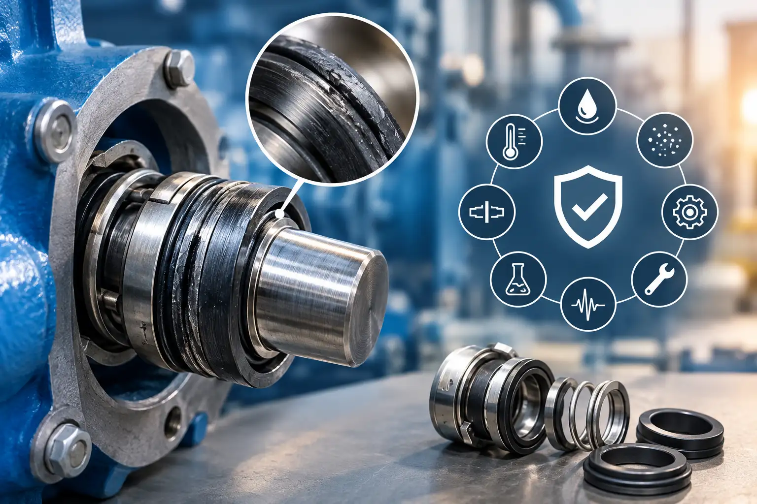
When a mechanical seal fails, the first instinct in many plants is simple: remove the damaged seal, install a new one, and restart the pump. That approach may restore operation today, but it often guarantees the same problem returns next month.
A true mechanical seal failure analysis does more than identify leakage. It asks why the seal was destroyed, what condition allowed the damage to develop, and whether the failure was caused by the seal itself, the installation, the process fluid, the pump hydraulics, or the sealing support system.
In industrial pumping systems, seals are rarely the only suspect. They are precision components operating inside a dynamic environment. Heat, pressure, vibration, solids, chemistry, and human decisions all influence their service life. If any one of these factors moves outside the design envelope, even a high-quality seal can fail early.
This guide explains the seven most common root causes of mechanical seal failure, how to recognize their physical evidence, and what maintenance and engineering teams can do to prevent repeated failures. It also connects failure analysis to broader reliability topics such as pump seal troubleshooting, seal material selection, API 682 sealing systems, and predictive maintenance for pumps and seals.
What Is Mechanical Seal Failure Analysis?
Mechanical seal failure analysis is a structured investigation used to determine why a seal stopped performing as intended. It combines physical inspection, operating data review, installation history, and process condition evaluation.
A proper analysis does not begin by blaming the seal manufacturer. It begins by collecting evidence.
The investigator examines:
- Seal face condition
- Elastomer and secondary seal damage
- Shaft sleeve wear or scoring
- Spring, bellows, or drive mechanism condition
- Gland plate and chamber geometry
- Flush, cool, barrier, or buffer system performance
- Pump vibration and alignment history
- Process temperature, pressure, and fluid composition
- Maintenance and installation records
The goal is to separate symptom from cause. Leakage is the symptom. The cause may be dry running, contamination, chemical attack, cavitation, misalignment, poor installation, or an unsuitable seal plan.
For a broader diagnostic framework, our Pump Seal Troubleshooting Guide 2026 explains how failure timing can reveal whether the problem occurred during commissioning, early operation, or long-term service.
Why Repeated Seal Failures Are More Expensive Than They Look
A failed seal is not only a parts issue.
When a pump seal leaks, the plant may face:
- Unplanned shutdowns
- Emergency maintenance labor
- Lost production
- Environmental exposure
- Safety risks
- Bearing and shaft damage
- Increased spare parts consumption
- Repair backlog pressure
In many cases, the cost of one repeated failure exceeds the cost of a complete reliability review. This is why mechanical seal failure analysis should be treated as an engineering activity, not just a maintenance task.
If the same seal type keeps failing in the same service, the problem is usually not bad luck. It is an uncorrected root cause.
Root Cause 1: Dry Running and Loss of the Lubricating Film
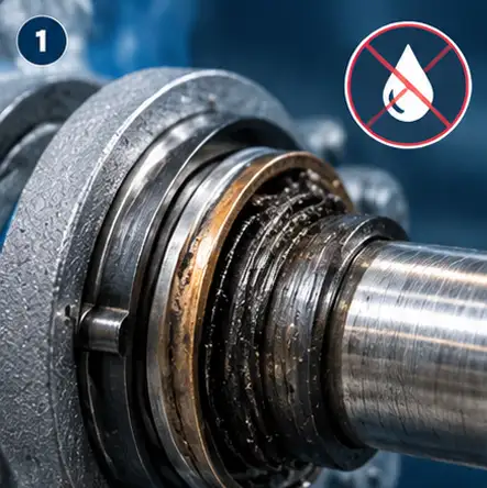
Dry running is one of the fastest and most destructive failure modes in rotating equipment sealing.
A mechanical seal depends on a thin fluid film between its faces. That film provides lubrication, cooling, and stability. When the pump runs without sufficient fluid, the film disappears. Friction rises sharply, temperature increases, and the seal faces can be damaged within seconds.
What Dry Running Looks Like on a Failed Seal
Common evidence includes:
- Darkened or blued seal faces
- Cracked carbon or resin-impregnated carbon
- Glazed or polished-looking faces
- Melted, hardened, or deformed elastomers
- Thermal checking on harder face materials
- Rapid failure shortly after startup or low-flow operation
Why It Happens
Dry running can be caused by:
- Low suction level
- Clogged strainer
- Closed discharge valve during startup
- Air entrainment
- Pump running off its best efficiency point
- Intermittent operation without proper protection
- Loss of flush flow in a seal support system
How to Prevent It
Prevention starts with process protection, not seal replacement.
Recommended actions:
- Install low-flow or dry-run protection
- Use level sensors on suction vessels
- Verify priming procedures before startup
- Monitor seal chamber temperature
- Review pump curves and minimum flow requirements
- Consider sealless or magnetic-drive solutions for highly sensitive services
- Use cartridge seals to reduce installation variability
For dirty or variable services, external flush arrangements can help maintain lubrication. In wastewater and slurry applications, our article Wastewater Pumps: Common Sealing Challenges and Their Proven Solutions explains why clean fluid injection and robust face materials are often combined to protect the seal environment.
Root Cause 2: Misalignment, Vibration, and Shaft Deflection
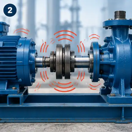
Mechanical seals are precision components. They expect the shaft to rotate smoothly, with controlled radial runout and axial movement. When alignment is poor, bearings are worn, couplings are misadjusted, or the shaft deflects under load, the seal faces can be forced into an unstable motion pattern.
How Misalignment Damages a Seal
Instead of maintaining a steady interface, the seal faces may experience a pumping effect. They separate and recontact rapidly. This breaks the fluid film, increases wear, and can cause uneven face damage.
Typical signs include:
- One-sided face wear
- Scoring on the shaft sleeve
- Cracking near the drive lug or anti-rotation tab
- Loose set screws
- Wear marks from secondary seals
- Vibration readings above normal baseline
- Repeated failure after seemingly correct installation
Common Sources
Misalignment-related seal damage often comes from:
- Poor coupling alignment
- Worn bearings
- Soft foot or baseplate distortion
- Thermal growth not accounted for
- Excessive shaft end play
- Pipe strain on the pump casing
- Impeller imbalance
- Cavitation-induced vibration
How to Prevent It
A seal cannot compensate for a sick pump.
Prevention measures include:
- Laser alignment during installation and after maintenance
- Bearing condition checks
- Shaft runout measurement
- Vibration baseline monitoring
- Pipe strain relief
- Foundation and baseplate inspection
- Use of cartridge seals where installation consistency is critical
Cartridge seals can be especially helpful because they reduce field setting errors. For demanding pump services, Qalalam cartridge options such as Mechanical seals Cartridge K33RBD and Mechanical seals Cartridge K34RBD may be considered where factory presetting and robust construction support reliability goals.
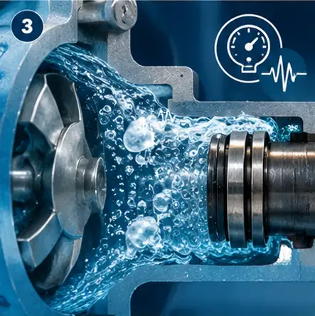
Root Cause 3: Cavitation and Pressure Transients
Cavitation is not only an impeller problem. It also damages seals.
When local pressure falls below the vapor pressure of the liquid, vapor bubbles form. As these bubbles collapse, they create shock waves, noise, vibration, and micro-jets. That energy is transferred through the pump internals and can reach the seal faces.
Seal Damage Associated with Cavitation
Evidence may include:
- Pitting on seal faces
- Micro-cracking
- Chipped or fractured harder face materials
- Disturbed secondary seals
- Erratic leakage during operation
- Noise or vibration that changes with pump flow
- Damage concentrated near the seal chamber
Why It Is Often Missed
Operators may see leakage and assume the seal is defective. But the seal may simply be the weakest component exposed to unstable hydraulics. Cavitation can also worsen during startup, turndown, or partial blockage conditions.
How to Prevent It
Corrective actions should focus on pump operating conditions:
- Verify NPSH available versus NPSH required
- Avoid operating too far from the pump curve
- Check suction line losses
- Remove strainer blockage
- Control flow rate properly
- Review system pressure fluctuations
- Consider inducers or pump redesign where needed
- Monitor vibration and acoustic signatures
In high-risk process environments, cavitation-related seal damage can be reduced by combining proper pump hydraulics with appropriate sealing support systems. For a wider view of sealing technology in demanding industries, see Advanced Mechanical Seals Boosting Efficiency in Oil & Gas.
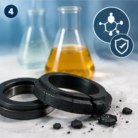
Root Cause 4: Chemical Incompatibility and Elastomer Degradation
Not all seal failures are mechanical. Many are chemical.
A seal may have excellent face materials but still fail because the elastomers, O-rings, gaskets, or secondary seals are not compatible with the process fluid, temperature, or cleaning chemicals.
What Chemical Attack Looks Like
Typical signs include:
- Swollen O-rings
- Soft or sticky elastomer surfaces
- Cracked or hardened rubber
- Loss of elasticity
- Blistering
- Decomposed gaskets
- Leakage from static joints even when seal faces appear acceptable
Why It Happens
Chemical incompatibility often results from:
- Selecting elastomers based on fluid name only
- Ignoring temperature effects on chemical resistance
- Using the wrong material for cleaning-in-place chemicals
- Assuming one elastomer works for all services
- Overlooking sour gas, amines, solvents, acids, or oxidizers
- Mixing incompatible lubricants during installation
For example, a material that performs well in water may fail rapidly in hydrocarbons. Another material may resist oils but degrade in steam or hot chemical solutions.
How to Prevent It
Material selection must be based on real operating conditions, not catalog assumptions.
Best practices:
- Identify all fluids contacting the seal, including flush and barrier fluids
- Review continuous and peak temperatures
- Check chemical compatibility charts
- Consider NACE or sour service requirements where relevant
- Validate elastomer selection with the seal supplier
- Inspect failed elastomers under magnification
- Avoid mixing incompatible greases or sealants
Our article How to Select the Right Seal Material for Oil, Gas & Chemical Industries provides a practical framework for matching elastomers and seal materials to process conditions.
Secondary sealing elements also deserve attention. Even a small O-ring issue can compromise an entire seal support system. For related guidance, review:
- Oil Seal vs O-Ring: Key Differences in Petrochemical Applications
- Why Do O-Rings Fail? Troubleshooting & Prevention Guide
- The Ultimate O-Ring Selection Guide 2025: Materials & Sizing
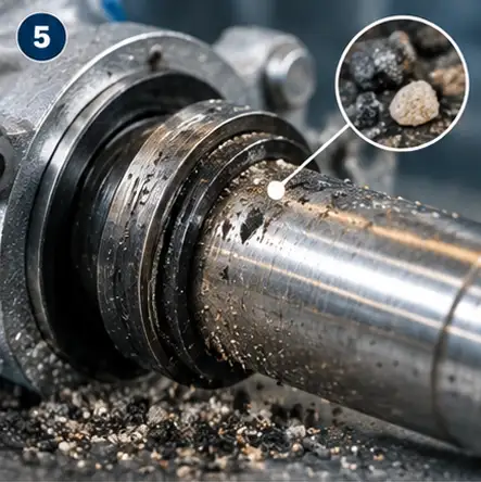
Root Cause 5: Contamination, Solids, and Abrasive Wear
Dirty fluids are brutal on mechanical seals.
Sand, grit, scale, catalyst particles, fibers, crystals, and polymer fragments can enter the seal interface and act like abrasive paste. Once particles become trapped between the faces, wear accelerates quickly.
Physical Evidence of Abrasive Failure
Look for:
- Grooves or scratches on seal faces
- Embedded particles in softer faces
- Polished wear tracks on the shaft sleeve
- Clogged flush lines
- Blocked strainers or cyclone separators
- Rapid leakage after startup
- Damage worse on the inboard or process side
Why Standard Seals May Not Survive
A seal that works well in clean water may fail in wastewater, slurry, or process streams with intermittent solids. The problem is not only hardness. It is also whether the seal chamber is being kept clean and cool.
How to Prevent It
Prevention requires both material selection and contamination control.
Recommended actions:
- Use harder face combinations where appropriate, such as silicon carbide-based pairs
- Install external flush plans for dirty services
- Add filtration or cyclone separation when solids are present
- Verify flush flow during commissioning
- Avoid relying on process fluid alone if it is abrasive or crystallizing
- Inspect seal chambers for particle accumulation
- Consider dual seal arrangements for severe service
In wastewater and slurry pumping, external flush and robust sealing design are often critical. The topic is covered in more depth in Wastewater Pumps: Common Sealing Challenges and Their Proven Solutions.
For high-risk or abrasive services, cartridge double seals can provide a more controlled sealing environment. Models such as Mechanical seals Cartridge K22RSD and Mechanical seals Cartridge K23RRD may be relevant where enhanced containment and pre-engineered installation are required.
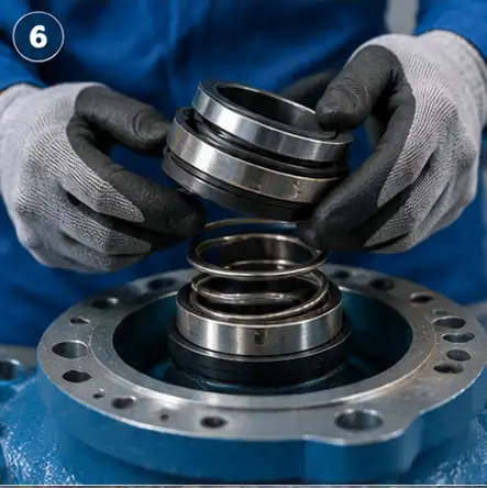
Root Cause 6: Improper Installation, Setting, and Handling
Even the best seal can fail early if it is installed incorrectly.
Installation errors are especially common in component seals, where setting dimensions, compression, cleanliness, and shaft preparation matter. Cartridge seals reduce some of this risk, but they are not immune to poor handling or incorrect mounting.
Common Installation Mistakes
Examples include:
- Wrong seal setting dimension
- Over-tightened gland bolts
- Damaged seal faces during handling
- Scratched shaft sleeve
- Dirt left in the seal chamber
- Missing or incorrect gasket
- O-ring rolled, pinched, or cut
- Wrong rotation direction assumed
- Failure to verify shaft runout
- Using incompatible lubricants during assembly
- Tightening the gland before confirming free movement
How Installation Failures Appear
Immediate or early failure is a major clue.
If a seal leaks within hours or days of installation, investigate:
- Setting error
- Dry running at startup
- Face damage during handling
- Misalignment
- Blocked flush line
- Wrong seal type
- Contamination in the chamber
How to Prevent It
A disciplined installation process is essential.
Best practices:
 Read More :
Oil Seal vs O-Ring: Key Differences and Applications
- Use installation checklists
- Train maintenance technicians
- Handle seal faces with clean gloves
- Keep components packaged until installation
- Measure shaft sleeve condition before fitting
- Verify gland flatness and bolt torque sequence
- Confirm rotation and operating direction
- Flush the system before startup
- Use cartridge seals for critical or repeat-failure services
Cartridge seals are often preferred when installation consistency is a major concern because they are factory assembled and preset. This reduces the chance of field measurement errors and helps standardize maintenance.
Root Cause 7: Wrong Seal Type or Inadequate Flushing Plan
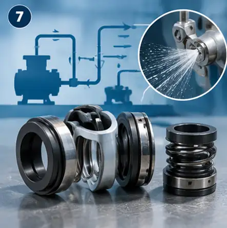
One of the most overlooked root causes is selecting a seal that does not match the service conditions.
A mechanical seal is not a standalone product. It is part of a sealing system. The seal type, face materials, elastomers, gland design, and flushing or barrier arrangement must all work together.
When the Seal Type Is Wrong
Examples:
- Using a single seal for hazardous or volatile fluid
- Using an unbalanced seal in high-pressure service
- Selecting carbon faces for highly abrasive fluid
- Using elastomer-secondary seals in extreme temperature without validation
- Specifying a component seal where cartridge reliability is needed
- Choosing a seal based only on shaft size, not process conditions
When the Flushing Plan Is Inadequate
A poor flush plan can destroy a good seal.
Common problems:
- No cooling where heat is the dominant issue
- No external flush where solids are present
- Blocked flush line
- Incorrect orifice size
- Barrier pressure too low or too high
- Contaminated barrier fluid
- No monitoring of dual seal support system
- Plan selected from an old datasheet without reviewing current process changes
For a deeper explanation of seal support arrangements, our article Mechanical Seals for Petrochemical Plants: API 682 Guide to Prevent Failure is a useful reference.
The choice between single and double seals is also critical. In high-pressure or hazardous services, a double seal with proper barrier fluid control can reduce risk significantly. See Double vs Single Mechanical Seals: High-Pressure Guide for a practical comparison.
How to Prevent It
Seal selection should be based on a full service review:
- Fluid composition
- Temperature range
- Pressure and pressure spikes
- Vapor pressure
- Solids content
- Lubricity
- Toxicity and flammability
- Emissions requirements
- Pump type and speed
- Startup and shutdown behavior
- Maintenance capability
- Available flush or barrier utilities
In many plants, the lowest-cost seal is not the lowest-risk seal. Total cost of ownership should guide the decision.
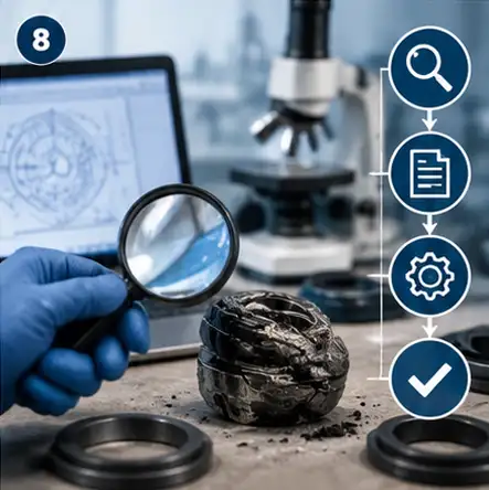
How to Perform a Mechanical Seal Failure Analysis: A Practical Workflow
If you want to stop repeated failures, use a consistent investigation method. The following workflow helps teams move from guesswork to evidence-based decisions.
Step 1: Preserve the Evidence
Before cleaning the seal, document its condition.
Take photos of:
- Seal faces
- Shaft sleeve
- Gland plate
- Elastomers
- Flush connections
- Barrier reservoir
- Wear patterns
Cleaning too early can remove valuable clues such as deposits, particles, or chemical residues.
Step 2: Interview the Operators
Ask what happened before failure:
- Did the pump trip?
- Was there low flow?
- Did the seal leak gradually or suddenly?
- Was there noise or vibration?
- Did process conditions change?
- Was the flush system active?
- Was the pump recently maintained?
Operator input often reveals the real story.
Step 3: Review Maintenance Records
Check:
- Installation date
- Seal model and setting
- Previous failures
- Alignment records
- Bearing replacements
- Flush line cleaning
- Barrier fluid changes
- Spare part batch numbers
Repeated failures on the same pump usually point to a systemic issue.
Step 4: Inspect the Seal Faces
Look for:
- Cracks
- Grooves
- Thermal discoloration
- Embedded particles
- Uneven wear
- Chipping
- Polishing
- Chemical attack
The face condition often identifies the dominant failure mechanism.
Step 5: Inspect Elastomers and Secondary Seals
Check for:
- Swelling
- Hardening
- Cracking
- Extrusion
- Cuts
- Compression set
- Loss of rebound
Even if the primary faces look acceptable, a failed secondary seal can cause leakage.
Step 6: Evaluate the Seal Support System
Review:
- Flush flow
- Cooler performance
- Strainer condition
- Cyclone separator operation
- Barrier pressure
- Accumulator status
- Alarm history
- Fluid cleanliness
A seal plan that is installed but not functioning is worse than no plan at all.
Step 7: Compare Against Process Conditions
Verify:
- Temperature
- Pressure
- Fluid properties
- Vapor pressure
- Solids
- pH or chemical aggressiveness
- Startup and shutdown sequences
Many failures occur because the process changed after the seal was specified.
Step 8: Assign the Root Cause and Correct It
Do not stop at “seal failed.” Classify the failure:
- Dry running
- Misalignment
- Cavitation
- Chemical attack
- Abrasive wear
- Installation error
- Wrong seal or plan
Then implement corrective actions and update maintenance procedures.
Prevention Checklist: How to Stop Mechanical Seal Failure Before It Starts
The best failure analysis is the one that prevents the next failure. Use this checklist during design, installation, and operation.
Design and Selection
- Confirm fluid composition and worst-case conditions
- Verify temperature and pressure range
- Check vapor pressure and flashing risk
- Review solids, fibers, crystals, or polymers
- Select face materials for wear and chemical resistance
- Select elastomers for compatibility and temperature
- Decide between single, double, or dual seal arrangements
- Choose cartridge seals for critical services
- Specify the correct API 682 flushing or barrier plan
- Ensure barrier fluid is clean and compatible
Installation
- Inspect shaft sleeve and chamber
- Measure runout and end play
- Clean all components thoroughly
- Follow setting dimensions carefully
- Use proper tools, not hammers or pry bars
- Lubricate elastomers with compatible material
- Verify gland bolt torque sequence
- Confirm rotation direction
- Check flush connections before startup
Operation and Maintenance
- Monitor temperature, vibration, and leakage
- Track barrier pressure and fluid level
- Inspect strainers and coolers
- Review alarm trends
- Train operators on normal versus abnormal behavior
- Use predictive maintenance where practical
- Record every failure and corrective action
- Standardize seal models where possible
Predictive maintenance can be especially valuable for detecting early warning signs. Our article AI Predictive Maintenance for Pumps & Seals explains how vibration, temperature, pressure, and leakage trends can help identify problems before catastrophic failure occurs.
Industry-Specific Failure Patterns Worth Watching
Different industries tend to produce different seal failure signatures.
Oil and Gas
Common issues include high pressure, sour service, hydrocarbon volatility, temperature swings, and abrasive produced water. Material compatibility and barrier system control are often critical.
Petrochemical
Aggressive chemicals, polymerization, crystallization, and strict emissions requirements can make seal support systems as important as the seal itself. For more context, see Mechanical Seals for Petrochemical Plants: API 682 Guide to Prevent Failure.
Wastewater and Slurry
Solids, fibers, grit, and variable chemistry cause abrasive wear and clogging. External flush and hard face materials are often part of the solution. Related reading: Wastewater Pumps: Common Sealing Challenges and Their Proven Solutions.
LNG and Cryogenic Service
Low temperature changes material behavior. Thermal contraction, embrittlement, and secondary seal loss can create failure modes that resemble mechanical damage but are actually temperature-driven. For a broader view, read How Global LNG Expansion Is Increasing Demand for Cryogenic Pump Sealing Systems.
Hydrogen Systems
Hydrogen’s small molecule size creates permeation and embrittlement concerns. Leakage control, material selection, and monitoring are especially important. See Hydrogen Pumps and the Future of Seal Technology.
Agitators and Mixers
Agitators can suffer from shaft deflection, intermittent operation, tank vapors, solids, and cleaning chemicals. Seal selection must account for speed, vessel conditions, and maintenance access. Qalalam agitator seal options include:
- Mechanical seals Agitator AUL44V
- Mechanical seals Agitator AUH33
- Mechanical seals Agitator AUH11B
- Mechanical seals Agitator AUH55
- Mechanical seals Agitator AIH21
- Mechanical seals Agitator AUH44
Quick Reference: Failure Evidence and Likely Root Cause
| Observed Damage | Likely Root Cause | First Investigation Area |
|---|---|---|
| Blued or cracked faces | Dry running or overheating | Flow, priming, flush, minimum flow |
| One-sided wear | Misalignment or shaft deflection | Coupling, bearings, runout |
| Pitting or micro-cracks | Cavitation or pressure transients | NPSH, suction conditions, vibration |
| Swollen elastomers | Chemical incompatibility | Fluid chemistry, temperature, material chart |
| Grooved faces | Abrasive solids | Filtration, flush plan, chamber cleanliness |
| Immediate leakage after install | Installation error | Setting, handling, torque, rotation |
| Chronic leakage despite new seal | Wrong seal type or poor plan | API 682 plan, barrier pressure, service review |
This table is not a substitute for full analysis, but it gives maintenance teams a faster starting point.
When to Upgrade from Component Seals to Cartridge Seals
If a plant experiences repeated failures, upgrading the seal design may be more cost-effective than continuing repairs.
Component seals can work well in clean, stable services. But they require precise field setting and are more sensitive to installation variation. Cartridge seals reduce many of these risks because they are assembled and preset by the manufacturer.
Consider cartridge seals when:
- The same pump fails repeatedly
- Maintenance staff turnover is high
- The service is hazardous or critical
- Installation errors are suspected
- Downtime cost is significant
- Standardization is needed across multiple pumps
- Dual seal or barrier system reliability is important
Qalalam cartridge seal options such as Mechanical seals Cartridge K22RSD, Mechanical seals Cartridge K23RRD, Mechanical seals Cartridge K33RBD, and Mechanical seals Cartridge K34RBD can be evaluated based on shaft size, pressure, temperature, fluid, and plant standards.
Frequently Asked Questions
What is the most common root cause of mechanical seal failure?
There is no single universal answer, but dry running, misalignment, contamination, chemical incompatibility, and improper installation are among the most frequent causes. The correct root cause can only be identified by examining the seal, the pump, and the process conditions together.
How can I tell if a mechanical seal failed because of dry running?
Dry running often leaves thermal evidence: darkened faces, cracking, glazing, melted elastomers, or rapid failure after startup or low-flow operation. If the seal damaged quickly and the pump had insufficient fluid at the seal face, dry running should be high on the investigation list.
Can misalignment cause a seal to leak even if the seal is new?
Yes. Misalignment, vibration, or shaft deflection can prevent the seal faces from maintaining a stable film. The seal may appear correct on paper but fail because the rotating environment is unstable. Alignment, bearing condition, and shaft runout should be checked before blaming the seal.
Why do O-rings matter in mechanical seal failure analysis?
O-rings and other secondary seals control leakage paths that the primary faces do not. A swollen, cracked, extruded, or improperly installed O-ring can cause system leakage even when the main seal faces are intact. For related guidance, see Why Do O-Rings Fail?.
Is a cartridge seal always better than a component seal?
Not always. Cartridge seals reduce installation variability and are often better for critical or repeat-failure services. However, component seals can be suitable for clean, low-risk applications where installation discipline is strong and cost is a major constraint.
How does an API 682 flushing plan prevent seal failure?
A flushing plan controls the environment around the seal. It can cool the faces, remove heat, dilute solids, prevent vaporization, or maintain barrier pressure. The wrong plan, or a blocked plan, can cause failure even with a good seal. More detail is available in Mechanical Seals for Petrochemical Plants: API 682 Guide.
Should I replace a failed seal with the same model?
Not automatically. If the failure was caused by process conditions, installation error, or an unsuitable seal type, replacing it with the same model may repeat the problem. First complete a failure analysis, then decide whether the correct action is replacement, upgrade, or system modification.
How can predictive maintenance help with mechanical seals?
Predictive maintenance monitors trends in vibration, temperature, pressure, leakage, and barrier fluid behavior. It can detect early warning signs before visible failure occurs. This makes maintenance planned instead of emergency. Learn more in AI Predictive Maintenance for Pumps & Seals.
Final Thoughts: Fix the System, Not Just the Seal
A mechanical seal failure is rarely just a seal problem.
It is usually a signal that something in the system is out of balance: too much heat, too many solids, unstable pressure, incompatible chemistry, poor alignment, incorrect installation, or an inadequate flushing plan.
Effective mechanical seal failure analysis turns a repeated maintenance headache into a reliability improvement opportunity. Instead of asking only “Which seal should we install next?”, plants should ask “What condition destroyed the last seal, and how do we remove that condition permanently?”
When teams combine proper seal selection, disciplined installation, correct API 682 support systems, material compatibility, and condition monitoring, they reduce downtime, improve safety, and lower total cost of ownership.
For further engineering reference, explore these related Qalalam resources:
- BEST CHOICE: Pump Seal Troubleshooting Guide 2026
- Double vs Single Mechanical Seals: High-Pressure Guide
- How to Select the Right Seal Material for Oil, Gas & Chemical Industries
- Wastewater Pumps: Common Sealing Challenges and Their Proven Solutions
- AI Predictive Maintenance for Pumps & Seals
If your plant is facing repeated seal leaks, the fastest way to stop them is not another replacement. It is a structured failure analysis that identifies the true root cause and corrects it before the next pump starts.